$9.95
165 in stock
- Ships in 1-2 days
- No Risk Guarantee
- 2-3 Year Warranty
Features
Technical Information
| Ship Weight | 0.19 lbs |
|---|---|
| Ship Dimensions | 3 × 2 × 1 in |
| Temperature Range |
FAQs
Frequently Asked Questions
Problem:
Sometimes your RemotePro® system doesn’t have enough power to keep your equipment alive for 24hrs per day and you really don’t need, for example a camera, to be powered on at night. Other times you want to be able to reduce your investment in solar panels and batteries because your equipment only needs to be powered up during certain times of the day.
Solution:
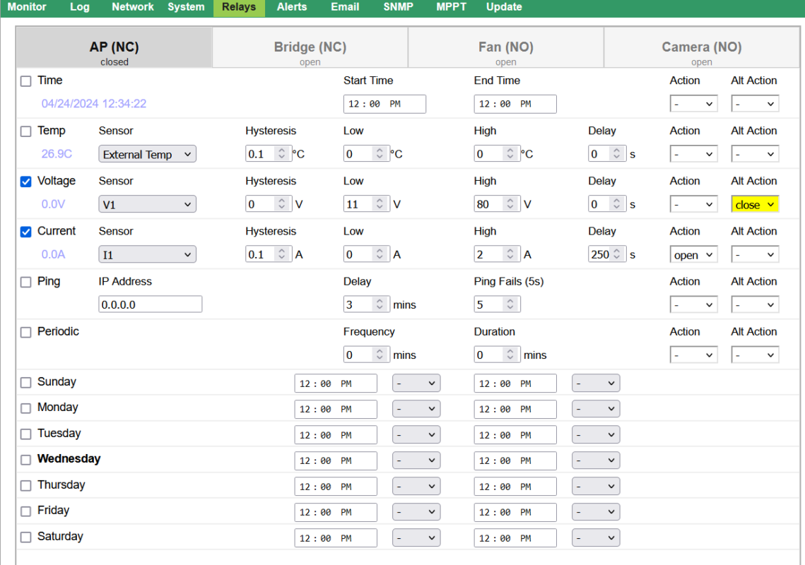
With the TPDIN® Monitor you can program Relay 1 (CH1) and Relay 2 (CH2) to operate only during certain times of the day. To set the unit to power up equipment only during certain hours connect one side of the power going to the equipment through Relay 1 (CH1) or Relay 2 (CH2).
Then set the Time Control for an ON time and an OFF time. The equipment will turn on at the ON Time and turn off at the OFF time.
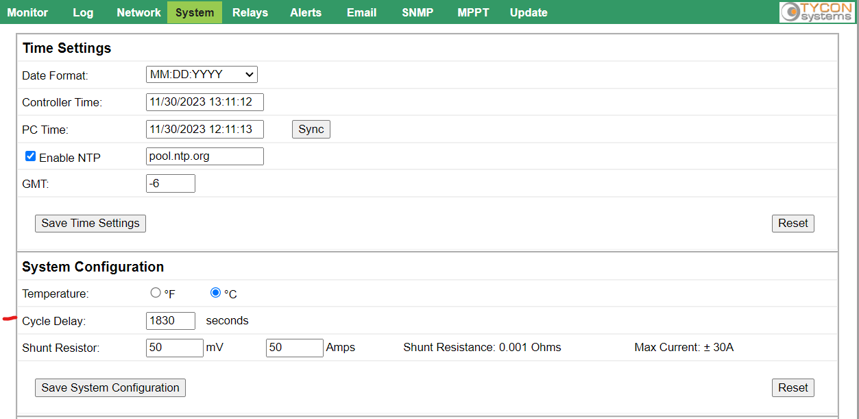
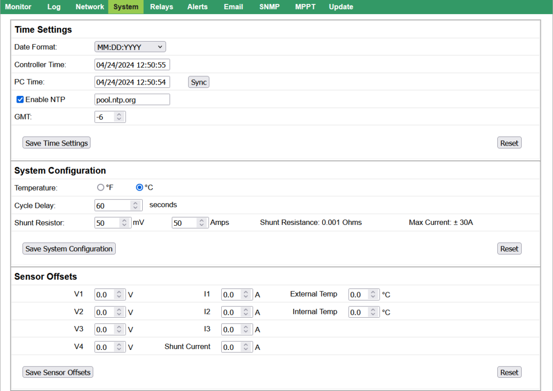
This will reduce the daily power consumption by only turning on the equipment during the hours that it is needed. In the example on the right, the Relay 1 will turn the equipment on at 6AM and off at 9PM. You can also combine both time-of-day control and periodic control by using both the Ping Control and Time Control. For instance, I may want to power up my camera and wireless only once every 30 minutes during the daylight hours for 3 minutes to transmit an image and then shut them down to conserve power. This can be accomplished by using the Ping Control and Time Control together.
- Set the Time Control for the desired-ON time and OFF time. In this case it’s ON at 6AM and OFF at 9PM
- Set the Ping control to ping a non-existent IP address.
- Set the Every(secs) to 180. This defines the ON Time for the relay. In this case we are setting to 180secs or 3 minutes.
- Set the Fails = 1 and Wait(secs) = 0.
- On the System Configuration page set the Cycle Delay to 1800 this defines how long the Relay will be Off. In this case it’s 1800 secs or 30 minutes.
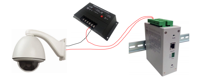
The ground between the V- load output on the MPPT solar controller and the TPDIN-Monitor-WEB3 V- needs to be isolated for the MPPT controller to sense the currents properly.
A TP-DCDC-1224 DCDC converter can be used to isolate the power and solve this issue.
The ground between the V- load output on the MPPT solar controller and the TPDIN-Monitor-WEB3 V- needs to be isolated for the MPPT controller to sense the currents properly.
A TP-DCDC-1224 DCDC converter can be used to isolate the power and solve this issue.
Make sure the unit is connected to the internet.
If set for static IP check to make sure on Network Page:
- Default Gateway address = address of your router
- DNS Address = valid DNS address.
Use Google DNS address 8.8.8.8 if you don’t have alternate DNS.
A communications problem during upgrade may have caused corruption in the flash memory or the “Upgrade and Reboot” button was double clicked or pressed twice.
Follow these steps to recover:
- Press and hold the reset button while powering up the unit.
- Release button as soon as you see a green Link LED on the RJ45 connector.
- Access the unit via the Discovery Tool or on its previous IP address and immediately go to Upgrade and re-load the firmware. Be careful not to double click the “Upgrade and Reboot” button.
Following are the existing TPDIN products and what type of SMTP they support:
| TPDIN-Monitor-WEB | Non SSL – Port 25 |
| TPDIN-Monitor-WEB2 | Non SSL – Port 25 ; SSL – Port 465 |
| TPDIN-Monitor-WEB3 | Non SSL – Port 25 ; TLS – Port 587 |
| TPDIN-SC48-20 V1 | Non SSL – Port 25 |
| TPDIN-SC48-20 V2 | Non SSL – Port 25 ; TLS – Port 587 |
How to Setup for Non SSL
In order to send email alerts with the TPDIN® series of products that don’t support SSL/TLS you will need to be able to send non-encrypted email via SMTP port 25.
If you don’t have access to a non-encrypted SMTP server on port 25, you can use the Google SMTP server address aspmx.l.google.com
Note: This SMTP server will only allow sending to a gmail address. If you need to send to a different address you can always forward the emails in the GMAIL settings.
When using this service leave the user name and password fields blank. Make sure to check the box on the TPDIN that says “Use user name as from field” if it exists.

How to Setup SSL/TLS
You can use GMAIL to send to any email address. GMAIL supports both SSL and TLS.
Use server “smtp.gmail.com” on port 465 for SSL or port 587 for TLS

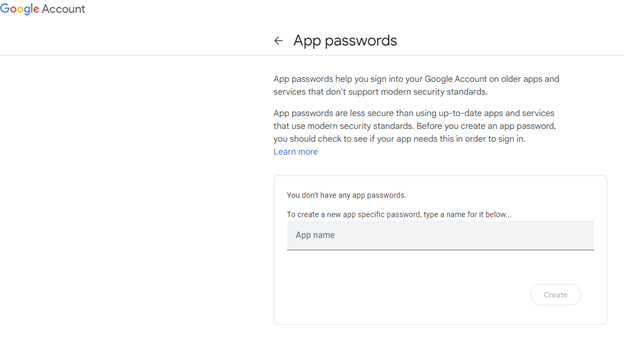
3. At the bottom of the screen:
- Select app and choose “mail”
- Select device and choose “other”
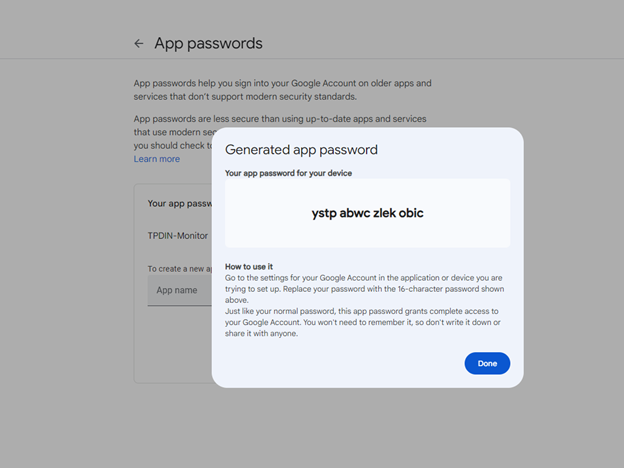
- Click on Generate
- This is the password you will use on your device(s).
- Enter the App Password that is a 16-character code in the yellow bar into your TPDIN email settings password field. You can copy and paste to do this. Click Save Email Settings and then Test Email Settings. Verify it will now send an email.
- If you don’t have the google account setup correctly at google, you will get a “Bad Username or Password” error from the TPDIN.
TPDIN-Monitor-WEB: username and password fields on the Network Page accept up to 10 characters.
TPDIN-Monitor-WEB2: username and password can accept up to 20 characters.
TPDIN-Monitor-WEB3: username and password can accept up to 24 characters.
TPDIN-SC48-20: username and password can accept up to 20 characters.
TPDIN-SC48-20 v2: username and password can accept up to 24 characters.
When you first receive the managed switch you will want to power it at 48VDC and then connect an RJ-45 from the unit to your network (switch, router etc.). Use the Tycon discovery tool to view the new device and double click on it to access the GUI. From there you can change the ports to different voltages.
TPDIN-Monitor-WEB: Hold down the reset button while powering up the TPDIN-Monitor-WEB and hold for 15 seconds then release reset button. This should set the unit back to factory defaults.
Note: Resetting to factory defaults doesn’t affect the IP address settings.
-TPDIN-Monitor-WEB2 and the TPDIN-Monitor-WEB3:
- Power up the unit. Wait at least 20 seconds. Press the reset button and hold for 10 seconds to reset to factory defaults.
- If the reset button is held for longer than 30 seconds, the unit will roll back to the last stable factory firmware.
- Only use this if the unit has an unrecoverable error.
TPDIN-SC48-20:
- There is a button on the top of the controller labeled FACTORY DEFAULT.
- Pressing and holding this button for over 5 seconds will reset to factory defaults.
You can use HTTP GET requests to enable or disable the relay controls. Assume the IP address of your unit is 192.168.1.77 Click here for the Linux Scripting.
Unofficial hack.
Note: This is an unofficial hack. Do this at your own risk.
You can change the CH3 and CH4 relays to Normally Closed by changing the position of a soldered jumper wire inside the unit.
Open the unit by removing all screws. Unsolder and move jumper from NO to NC. Make sure soldering is good. Be sure not to damage any surrounding components.
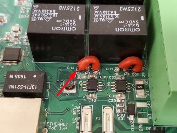
If you need to return the product for warranty, you must put the unit back to original configuration or the warranty request may be rejected and/or you may be charged a restocking fee.
Following are the existing TPDIN products and what type of SMTP they support:
| TPDIN-Monitor-WEB | Non SSL – Port 25 |
| TPDIN-Monitor-WEB2 | Non SSL – Port 25 ; SSL – Port 465 |
| TPDIN-Monitor-WEB3 | Non SSL – Port 25 ; TLS – Port 587 |
| TPDIN-SC48-20 V1 | Non SSL – Port 25 |
| TPDIN-SC48-20 V2 | Non SSL – Port 25 ; TLS – Port 587 |
Setting up Non SSL
- In order to send email alerts with the TPDIN® series of products that don’t support SSL/TLS you will need to be able to send non-encrypted email via SMTP port 25.
- If you don’t have access to a non-encrypted SMTP server on port 25, you can use the Google SMTP server address aspmx.l.google.com
- Note: This SMTP server will only allow sending to a gmail address. If you need to send to a different address you can always forward the emails in the GMAIL settings.
- When using this service leave the user name and password fields blank. Make sure to check the box on the TPDIN that says “Use user name as from field” if it exists.

Setting up with SSL/TLS
- You can use GMAIL to send to any email address. GMAIL supports both SSL and TLS.
- Use server “smtp.gmail.com” on port 465 for SSL or port 587 for TLS

NOTE: This only works with the original TPDIN-MONITOR-WEB.
It is not implemented in the newer TPDIN-MONITOR-WEB2. You can use the ability of telnet to connect to the TPDIN-Monitor-WEB TCP port and use the HTTP interface to control the unit. Connect to the device through telnet by designating the TPDIN-MonitorWEB units IP address and the communications port (typically port 80) as follows:
- telnet (ip address: 80)
To get the present values of the TPDIN-Monitor-WEB issue the following telnet command:
- GET /status.xml HTTP/1.1
TELNET will respond with latest data readings in the following format:
- HTTP/1.1 200 OK Connection: close Content-Type: text/xml Cache-Control: no-cache
1 1 1 1 0.0 0.0 0.0 0.0 0.0 0.0 0.0 0.0 45.1 24.0
To toggle a relay from one state to another, for instance ON to OFF, use the following command and define which relay(led) to toggle.
Note: led1=relay1, led2=relay2, etc. Running the command again will toggle the relay from OFF to ON. GET /leds.cgi?led=1 HTTP/1.1 GET /leds.cgi?led=1 HTTP/1.1
You must be logged in to post a review.
Related products
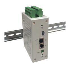
TPDIN3 Remote Monitor/Ctrl, Web Voltmeter
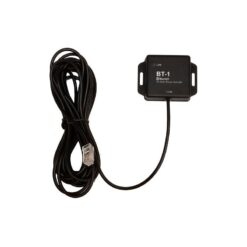
Weatherproof Bluetooth interface for TP-SC24-20-MPPT, TP-SC24-40(N)-MPPT, TP-SC48-60-MPPT Controllers, Up To 15m Range, 5m Interconnect Cable. Enables Wireless Remote Monitoring/Control.
Lock Kit for RPMS Solar Trailers. Tongue Lock for 1 7/8" to 2 5/16" + Padlock for solar panel tilt lock. Common Keyed.
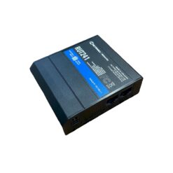
Teltonika RUT241 Bundle for remote cellular access. Includes: 150GB of RMS data , 1 yr RMS Remote Access, DIN Rail Mount, AC/DC power supply, DC Power Cable and External Weatherproof MIMO mobile antenna.
Tycon Systems Remote Management System (RMS) Single Credit. Enables remote connection to RMS for 1 device for 1 month
Tycon Systems Remote Management System (RMS) Access Credit 12 Month Pack. Enables remote connection to RMS for 1 device for 12 months or 12 devices for 1 month.
RMS Data Pack with 150GB of data which should last 5-10 years with normal use.






Reviews
There are no reviews yet