RPPL2448-20L-30
RemotePro6.5W,20Ah Lithium Batt,30W Sol,24/48V Dual Input PoE
User Guide
Note: Lithium Batteries can only ship to continental USA destinations. Lithium Batteries are not returnable unless you are certified to ship Hazardous Materials.
$529.95
In Stock Soon
- Ships in 1-2 days
- No Risk Guarantee
- 2-3 Year Warranty
Features
Applications
Description
Technical Information
| Ship Weight | 24.5 lbs |
|---|---|
| Ship Dimensions | 29 × 19 × 16 in |
| Battery Voltage | |
| Battery Capacity | |
| Solar Capacity | |
| Enclosure Type | |
| Controller Type | |
| Cont. Watts w/ 6 hrs Peak Sun |
FAQs
Frequently Asked Questions
Systems are shipped with everything that is needed except the mounting pole or tower and CAT5 cables (if needed to interconnect equipment).
Note: For 720W and 1300W solar systems, they come with the mounting pole included.
LIT is a battery settings mode. When switching to LIT, the S parameters should be the same as the previous default settings.
When battery voltage falls below 10V the battery BMS disconnects the battery discharge. As soon as there is PV voltage the battery BMS connects the charge and discharge. We recommend the customer set the LOAD Output turnoff at 11V so tha load disconnects before the battery BMS disconnects the discharge.
We recommend that you just leave the parameters set to AGM Lead Acid. This is how the Lithium battery BMS is designed. The AGM Lead Acid settings in the charge controller are compatible with the battery BMS.
You won’t see voltage spikes when connected to the battery (BMS), even if the battery BMS disconnects the discharge. No firmware updates are available or needed to switch from AGM lead acid to lithium.
At the recommended max distance with a clear line-of-sight and minimal external interference, the EZ-Bridge® will perform as advertised. However, if there are obstacles in the path or excessive external wireless interference or multipath reflections, some throughput slowdown may be noticeable.
There are a couple reasons why the load output on the controller will turn off.
- If the batteries get too low (11V for 12V battery and 22V for 24V battery 44V for 48V Battery) the load output will turn off. This is to save the batteries from over-discharge. The load output will turn back on when the batteries get charged from the solar panel.
- Motors, pumps and inverters cannot be connected to the load output of the controller, or it will overload and turn off. Instead connect motors, pumps and inverters to the battery through a high current power relay. The relay will be connected and controlled by the load output of the solar controller.
All RemotePro systems with a 720W solar array or larger will come with a top of pole mount and a 6 inch round, 72 inch long pole that needs to be anchored to a concrete footing.

https://tsi.tyconsystems.com/html/nrel_lookup.htm
Follow the link next to “Average Hours of Peak Sunlight per Day” field. Enter your zip code or city state to look up average peak sun hours each month. Alternatively, NREL (National Renewable Energy Lab) provides a free tool called “pvwatts”
” https://pvwatts.nrel.gov/ ” for more specific data in more locations and more detailed information. Be sure to change the “tilt angle” to optimize for winter sun in your area.
We need to know the load in watts for each piece of equipment you plan to use. We also need to know the operational voltage for each piece of equipment and if it is powered through wires or PoE. A good way is to send us a spec sheet for the equipment that you plan to power, and we can analyze the given information to size out the best system for you. For solar systems it’s important to know Peak Sun Hours at the site so we need to know where you plan to deploy the system. Provide us with zip code or city/state/country.
LIT is a battery settings mode. When switching to LIT, the S parameters should be the same as the previous default settings.
When battery voltage falls below 10V the battery BMS disconnects the battery discharge. As soon as there is PV voltage the battery BMS connects the charge and discharge. We recommend the customer set the LOAD Output turnoff at 11V so tha load disconnects before the battery BMS disconnects the discharge.
We recommend that you just leave the parameters set to AGM Lead Acid. This is how the Lithium battery BMS is designed. The AGM Lead Acid settings in the charge controller are compatible with the battery BMS.
You won’t see voltage spikes when connected to the battery (BMS), even if the battery BMS disconnects the discharge. No firmware updates are available or needed to switch from AGM lead acid to lithium.
Minimum Equipment Needed: Good digital voltmeter which will display DC Volts for Battery Voltage. Measure battery voltage at the charger/controller System Voltage Expected Battery Voltage (charging Expected Battery Voltage (not-charging12V – 13.5VDC to 14.5VDC 11VDC to 13VDC 27VDC to 29VDC 22VDC to 26VDC 48V 54VDC to 58VDC 44VDC to 52VDC Solar Panel Voltage The solar panel should be disconnected and receiving sunlight Solar Panel Voltage Expected Output Voltage 18-22VDC 24V 32-38VDC 48V 64-76VDC
- FUSE: The battery cables have a protection fuse. If no power, check the fuse to see if it is blown. Replace with type is 3AG 20A 250V Glass Cartridge (Shurter 0001.1037 or similar). Available at Digikey and Mouser. LEDs for Battery/Solar Charge Controllers TP-SCPOE Charge Controller
- LOA – LOA Light will be on, and the load outputs (Green connector and RJ45 POE Out) should have voltage when the battery is within the usable range. When the battery drops to below 11.2V the LOA will turn off. It won’t turn back on till the battery reaches 12V. On 24V systems LOA turns off at 20V and back on at 24V
- POE – The POE LED will only show when the controller has a POE input in the bottom connector.
- CHA – will be steady state when charging and it will be flashing when the controller is float charging the batteries.
- SOL – The SOL LED will be on whenever there is voltage on the solar input.
- FUSE – There is a battery fuse in the front of the controller. Fuse type is 5mm x 20mm 10A 125V (Littlefuse 0233010.MXP or similar)
TP-BCxx-300 High-Capacity UPS Charge Controller
Before Troubleshooting Make Sure:
- back voltage switch is set for your AC voltage (115VAC or 220VAC)
- Battery type is set to GEL (for GEL or AGM) or WET for automobile type batteries.
- the Battery Switch on the front is switched to ON. This can be switched to OFF to disconnect the battery from the charger.
- LOAD – Load power is on. The load will turn off when battery voltage is too low and will turn back on when battery voltage reaches a stable voltage.
System Voltage OFF ON 12.6V 24V 21.5V 25.2V 48V 40V 51V
- PWR – AC Power is ON
- BATT – Battery is connected.
- CHD – Battery is fully charged and is float charging.
- CHG – Battery is charging.
TP-SC24-20 Solar Charge Controller
- RED LED – steady state when charging and flashes when batteries are charged and in float charge.
- BATTERY STATUS LED – Green 100%, Yellow 70%, Red 30%. Flashes when battery is very low.
- Green LED – Load output is on. If light is flashing, then the load was drawing too much current (>20A) The load output will turn off automatically when the battery voltage is too low and turn back on automatically when the battery voltage is stable.
Use the ON/OFF button to manually turn off power to the load.
System Voltage OFF ON 12V 10.7V 12.6V 24V 21.4 25.2
Batteries
When testing batteries that are wired in parallel, you must disconnect the battery, so it is isolated from other batteries. When batteries are wired in series you can test each battery without disconnecting them. A fully charged 12V battery will have a battery voltage greater than 12.5VDC without a load.
To see if you have a bad cell, disconnect any load and fully charge the battery, wait a few minutes, measure and record the battery voltage, wait at least 15-30minutes and measure the battery voltage again. The voltages should be within about 0.5V of each other. If the 30minute measurement is too low, then the battery is not good and should be replaced. Tycon Batteries are designed to be charged with Tycon Chargers that are designed for AGM or GEL batteries. Using automobile chargers can be used in an emergency but they shouldn’t be left connected to the battery for a long time or the battery will be damaged. We recommend not to exceed 4hrs if connected to an automobile battery charger. And only use for emergencies, not for regular charging. Tycon Batteries should never be left in a discharged state, especially in cold weather. If your UPSPro® or RemotePro® system is having charging issues, be sure to make sure that you disconnect the load and leave the batteries in a charged state while troubleshooting. Leaving the batteries in a discharged state for a few days or a week can kill the battery, permanently.
RemotePro® and UPSPro® systems are designed to maintain proper battery charge within a defined range. Our systems have protections for over-discharge of batteries but batteries also self-discharge over time, so if they are left without any charge or maintenance for a long time (normally over 6 months) they will continue to self-discharge. Our systems are not designed to restore a battery function if the battery gets over discharged. Our systems work within the range of 0% (13VDC) to 100% discharge (10VDC) on batteries. If batteries are less than 10VDC the user must recondition the battery by charging the battery with a good quality automotive battery charger (6A to 25A). We find that manual type chargers work best.
- Troubleshooting Battery Problems: Measure battery voltage of individual batteries. Voltage should be >10V. If less than 10V* the battery must be reconditioned. If there are multiple batteries, measure all batteries and compare the voltages. They should be within 1V of each other. If some batteries are lower. Recondition the low voltage battery or all the batteries to get them back to a balanced starting point.
- Reconditioning Batteries: Recondition batteries by charging for no more than 24hrs with a good quality automotive battery charger. Let batteries sit for another 24 hours and then measure voltages. A fully charged battery will be around 13V. If voltage drops below 12V after 24hours, the battery cannot hold a charge and needs to be replaced. Note: On the large ground mount AL enclosure, the batteries are 6V batteries, so the minimum voltage is 5V.
Most often this might be caused by loose or incorrect connections, or the product is designed for a different application. First check the installation manual to be sure all connections are correct, and that the device is designed to supply the voltage for your application. If all connections are correct, check the power supplies. Are the batteries charged sufficiently for the load?
If it is a solar charge controller, are the solar modules connected correctly and are they receiving good sunlight to operate?
Always best to review each component manual to ensure a safe and successful installation. The most common problem we see is customers bought a solar controller designed for 12VDC battery, but they have the batteries wired for 24VDC or vice versa.
The second most common problem is that the batteries are low voltage, and the controller shuts off the load output (Low Voltage Detect Function). The controllers will turn off the load at around 11V (22V for 24V battery systems).
We have a free system requirements calculator located at: https://tyconsystems.com/tycon-support/tycon-calculators/
You can use the online calculator or follow the guide below to determine solar requirements.
First calculate the total watts required for your equipment. Let’s assume 50W. Let’s assume your equipment will run 24hrs per day. 50W x 24hrs = 1200Wh; so, each day you are consuming 1200W. Figure out your worst-case winter sun in your area; let’s assume it’s 3hrs peak sun per day. So, with 3hrs of sun you need to generate 1200W of power. 1200W per day equipment load / 3hrs sun per day = 400W of solar panels *** This is the absolute minimum amount of solar you would require. With solar it’s always a good rule of thumb to add at least 20% additional capacity, so the recommended would be 500W minimum of solar panel capacity to support 50W equipment load with 3hrs of sun per day.
1 Peak Sun-hour = 1000 Wh/m or 1kWh/m.
The Sun provides approximately 1000 Watts of power per square meter of area at Earth’s radial distance from the Sun. For every 1 hour the Sun provides that power, the Energy applied to that square meter is equal to 1000Wh. (Energy = Power x Time) Due to the Earth’s curvature and rotation, 1 square meter of the Earth’s surface does not always get the full 1000W of power the Sun is providing. For simplicity of calculations specifically for solar system performance, we add up all of the Solar Energy provided to 1 square meter in a specific location over the course of a day, or average day of a year, and divide it by the standardized power of 1000W/m.
This provides an easy to deal with unit of Average Solar Energy Irradiance per day in a location… or Peak Sun Hour. So, even though sunrise to sunset may be 12 or more hours… the Sun at 5 to 6 PM is not nearly as strong as the sun from 11AM to 12PM. Peak Sun-Hours allows us to mesh all those bits of energy together to 1 average unit for easier calculations for energy production.
There is a free calculator at: https://tyconsystems.wpenginepowered.com/calculators/
You can use the online calculator or follow the guide above: To figure out how long a battery backup system will keep your equipment powered there is a simple calculation you can do ((Battery Capacity (Ah) x Battery Voltage (12V)) x Percent Discharge (50%)) / Your Equipment Load (Watts)
So, let’s say you’re 12V battery capacity is 100Ah and your equipment load is 50W. We use 50% discharge because you really don’t want to discharge batteries much more than 50% if you want them to have a long life 100Ah x 12V = 1200Wh. 1200Wh * 0.5 (50% discharge) = 600Wh (adjusted battery capacity) 600Wh / 50W = 12hrs backup time. As you can see in the above example, with 100Ah of battery and 50W load and no sun, the batteries will provide at least 12hrs run time. Be sure to size the batteries for your worst-case scenario.
Factors that contribute to the time to recharge:
- Your load that is drawing power from the batteries
- The battery capacity
- The amount the batteries are discharged.
- The amount of input power available to recharge the batteries.
Let’s assume you have a Tycon RPSTL12/24M-200-340 RemotePro solar power system. This system has 200Ah of batteries and 340W of solar. Let’s assume your Load is 1.5A @ 24V. To make calculations easy, you want to convert battery capacity and load to watts:
- Battery Capacity: 200Ah * 12V = 2400 Whrs
- Load Power: 1.5A x 24V = 36W
Scenario#1 Batteries are fully discharged, and we are recharging with solar.
- 2400Whrs battery capacity / (340W Solar – 36W Load) = 2400/304 = 8hrs to fully recharge the batteries.
Scenario#2 Batteries are 50% discharged and we are recharging with solar– This is the most common scenario
- (2400Whrs battery capacity / 2) / (340W Solar – 36W Load) = 1200/304 = 4hrs to fully recharge the batteries.<
Scenario#3 Batteries are 50% discharged and we are charging with an AC powered 600W battery charger.
- (2400Whrs battery capacity / 2) / (600W Battery Charger – 36W Load) = 1200/564 = 2.1hrs to fully recharge the batteries.
That will depend on your application. Mounting your enclosure and solar panels high above the ground will discourage vandalism. It’s important to mount the solar panels above any obstacles that may cause shade. Maximum sunlight exposure is most important. Mounting the enclosure directly below the solar panels is ideal to shade the enclosure and keep cool.
These are the autonomy calculations
Autonomy = Battery Ah x Battery Volts = Battery Watt Hrs * 50% battery discharge max = Battery Watt Hr Capacity / Ave Load in Watts = Autonomy Hrs
Ex:
Battery Ah = 180Ah
Battery Volts = 12V
Ave Load – 50W
180AH x 12V = 2160WHrs * 0.5 = 1080WHrs / 50W = 21.6hrs Autonomy
The battery’s voltage should always be higher than it’s standard voltage (12, 24, 48VDC) in order for it to run equipment. For example: 12VDC battery at float charge should be 13.5-13.8VDC. If the battery is fully charge but the voltage fails to reach 10.5V, chances are it has a dead cell or two.
You can add a 4.5” double hinged zinc plated safety hasp to secure the door on the Tycon ENC-ST-23x14x12 enclosure with a padlock.
An example of a suitable double hinged safety hasp can be found on Amazon or your local hardware store:
“https://www.amazon.com/dp/B0000CBIEL“
The safety hasp can be mounted to the enclosure using screws or rivets.
Be sure to waterproof the screws or rivets with silicon to prevent water leaks into the enclosure.
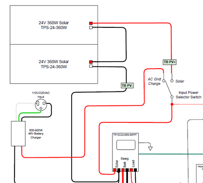
The following wiring diagram shows how to add an AC powered battery charger to the RemotePro system to provide supplemental charging of the batteries.
Automobile batteries are designed as high current starting batteries and are not designed for low current applications such as solar systems. The life of automobile batteries will be very short. We recommend using quality AGM, GEL or LiFePO4 batteries, which are designed for solar applications.
Most of the Tycon RemotePro® systems come with a 20′ 12AWG cable. Sometimes a customer may want to mount the solar panels at a different location than the solar controller/batteries. This can be done as long as you understand that if you extend the cable without increasing the wire diameter (AWG) you will create more loss in the cable run. There is a handy cable loss calculator that can be found at: https://www.calculator.net/voltage-drop-calculator.html
Using this calculator, you can find the loss with a given amperage, cable AWG and cable length.
The best way to reduce cable loss is to minimize the amperage travelling through the cable. For a given amount of watts, as the voltage goes up, the current (amps) goes down. For instance look at using a 160W solar panel system at different voltages. 160W/12V = 13.3A 160W/24V = 6.7A 160W/40V = 4A
A big advantage of using an MPPT solar controller is that the MPPT controller can typically handle up to 100V on the solar input and still charge a 12V or 24V battery. In our example of a 160W solar array, the array is made up of two 80W 12V solar panels. Each panel puts out about 20VDC. If you wire the panels in series the voltage adds to about 40V. You can see in the above example that with 160W solar array and 40V configuration, the current drops to only 4A which will result in a very low cable loss as compared to 13.3A in a 12V configuration using a PWM solar controller.
If using an MPPT controller isn’t an option for your application, the options you have would be to
- use the highest battery voltage possible
- use a larger wire diameter (AWG).
The 12AWG 20′ cable that ships with the systems can be extended by using a larger diameter wire like 10AWG or 8AWG or even larger. The Tycon PWM solar controller can handle as large as 10AWG wire but you can cut the 12AWG 20′ cable and use it to connect to the solar controller and solar panel and in between, use a long 8AWG or 6AWG cable and connect to the 12AWG wire using wire nuts. Using the larger diameter wire for the long runs will reduce your cable loss. The very short runs of 12AWG wire will have insignificant loss.
You may need to add additional panels or batteries in order to allow new equipment to be introduced.
- You can calculate it by going to: “https://tyconsystems.wpenginepowered.com/calculators”
- You will input your new total power draw, peak sunlight hours and any additional battery backup requirements to determine if more solar panels or batteries need to be added.
You must be logged in to post a review.
3D Model Viewer

Controls
×- Rotate with the left mouse button.
- Zoom with the scroll button.
- Adjust camera position with the right mouse button.
- Double-click to enter the fullscreen mode.
- On mobile devices swipe to rotate.
- On mobile devices pinch two fingers together or apart to adjust zoom.
- On mobile devices 3 finger horizontal swipe performs panning.
- On mobile devices 3 finger horizontal swipe performs panning.
Related products
TPDIN3 Remote Monitor/Ctrl, Web Voltmeter
Lock Kit for RPMS Solar Trailers. Tongue Lock for 1 7/8" to 2 5/16" + Padlock for solar panel tilt lock. Common Keyed.
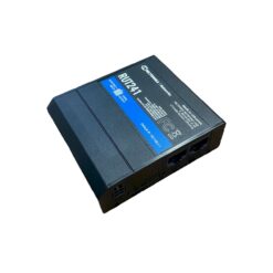
Teltonika RUT241 Bundle for remote cellular access. Includes: 150GB of RMS data , 1 yr RMS Remote Access, DIN Rail Mount, AC/DC power supply, DC Power Cable and External Weatherproof MIMO mobile antenna.
Teltonika RUT241 Bundle for remote cellular access. Includes: 150GB of RMS data , 1 yr RMS Remote Access, DIN Rail Mount, AC/DC power supply, DC Power Cable and External Weatherproof MIMO mobile antenna.
Tycon Systems Remote Management System (RMS) Single Credit. Enables remote connection to RMS for 1 device for 1 month
Tycon Systems Remote Management System (RMS) Access Credit 12 Month Pack. Enables remote connection to RMS for 1 device for 12 months or 12 devices for 1 month.
RMS Data Pack with 150GB of data which should last 5-10 years with normal use.







Reviews
There are no reviews yet