EZBR-5AC

(2 customer reviews)

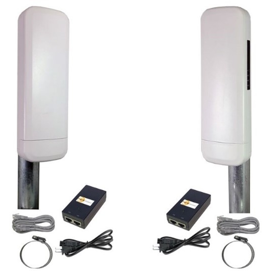
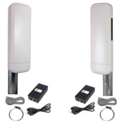
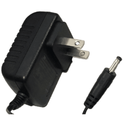
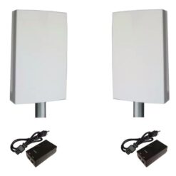
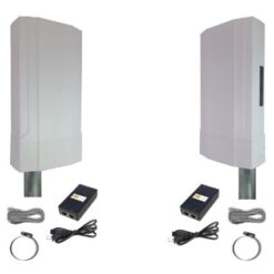
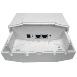
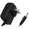
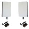
EZ-Bridge 5AC, 5Ghz 900Mb 3 Mile 802.11AC Point to Point Wireless Plug and Play Bridge Kit. Includes 2 Wireless Bridges, 2 Pole Mounts, 2 CAT5 Patch cables, 2 48V PoE Injectors

Spec Sheet
User Guide

Key Features:

• Operation up to 3 miles with good line of sight
• Up to 900 Mbps throughput
• True Plug and Play
• Operating in the 5GHz unlicensed frequency spectrum
• Complies with the 802.11a/n/ac standards

$299.95

410 in stock

  • Ships in 1-2 days
  • No Risk Guarantee
  • 2-3 Year Warranty

The EZ-Bridge® 5AC is a high power 25dBm (316mW) outdoor wireless bridge system operating in the 5GHz unlicensed frequency spectrum providing throughput up to 900 Mb/sec. It complies with the 802.11a/n/ac standards to insure interoperability. The EZ-Bridge® 5AC creates a transparent wireless bridge between two networks up to 3 miles apart with good line of sight. It supports VOIP, VPN, multiple MAC addresses and DHCP across the wireless link. It is the perfect plug and play solution for connecting the networks in two or more buildings, internet access sharing, remote video surveillance or remote network access. Multiple EZ-Bridge® 5AC units can be connected in a mesh configuration to allow interconnecting more than two sites.
With its password verification, MAC address authentication, SSID suppression and advanced WPA encryption, the system provides strong wireless data security.
Installation is a snap because of the plug and play features which have been built into the system. Just install the antennas and plug in the PoE power inserters. The units will automatically find their peer and create a secure wireless network link. If changes to the pre-configured settings are desired, they can be easily done thru the builtin web interface from any point on either side of the network. There are no drivers or software that needs to be loaded to the computer.
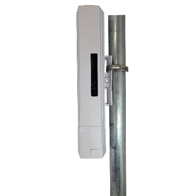
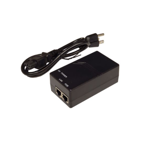
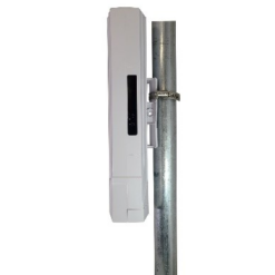
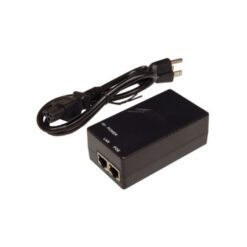
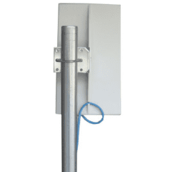
The EZ-Bridge® 5AC comes complete with all the electronics that are needed for a point to point wireless network bridge installation; including 2 powerful 15dBi 802.11a/n/ac MIMO antennas with built-in high power electronics, Stainless Steel hose clamp to accommodate 1-2” pole (or wall mounting), 48V PoE (Power over Ethernet) power inserters with auto-ranging 120/240VAC input, and one 3ft Cat5 Ethernet patch cable. Customer needs to supply CAT5/6 cabling between the power inserter and the antenna.

Technical Information

Ship Weight 8 lbs
Ship Dimensions 14 × 10 × 10 in

FAQs

Frequently Asked Questions

What makes the HD model different?

The HD model comes with Power over Ethernet inserter/power supplies with built in Ethernet and PoE surge protection. They also come with two 75′ Shielded and outdoor rated CAT5 cable assemblies.

These protections help to ensure long life in harsh environments.

My TyconOS/Ultra Discovery Tool Does Not Run!

The TyconOS and the Ultra Discovery Tool needs Java installed on your computer in order for it to run.

  1. Please download the latest version of Java on their official website “https://java.com/en/
  2. Once you’ve installed Java you should be able to run the discovery tool.

If you are running Windows 7 and the discovery tool Does not run, you would need to use a different network scanning tool like Advanced IP Scanner “https://www.advanced-ip-scanner.com/

The EZ Bridge will show up as “Compex Systems” under the manufacturer name.

If you get the message: “Unable to transmit discovery message” Check your network connectivity and ensure that no other instances of this program are running,

3. Check all the running programs in your task bar, and make sure the discovery tool is not running. You may also restart your computer to make sure that no other instances of the discovery tool are running.

If when you’re opening the discovery tool and a different program runs (like Internet Explorer asking you to download something or Adobe Reader shows up), you will need to make sure that .jar files are associated with Java. Jarfix is a small program that you can run to reassociate .jar files with Java. You can download Jarfix here:

http://johann.loefflmann.net/downloads/jarfix.exe

How to adjust multiple bridges distance optimization

Using 1 Side A and have it connected to the 2 remote units to eliminate interference from 1 side to the other. 


First thing you need to do is to make sure both remote devices have the same SSID  as the AP you are going to use and remove the AP you are going to keep as a spare. 

Then log in on the AP or Side A that stays in place and go into the device and change the distance Optimization settings. 


NETWORK >> WIFI  >> EDIT  >> Advanced Tab >>  Uncheck Distance Optimization box >>  Add 50 Meters to the distance of the unit that is farthest away from Side A into the distance line  >> Then click on Save and Apply. 


Can I Use the Second Ethernet Port to Link 2 Separate Access Points Together?

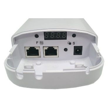
The two ethernet ports under the antenna can accept 12-24V PoE. They are used to power on the antenna. They will not provide any PoE out. The two ports also act like a switch. A device connected to the spare ethernet port will connect to the same network as the EZ Bridge antenna.

Will my speed slow down at extended distances?

At the recommended max distance with a clear line-of-sight and minimal external interference, the EZ-Bridge® will perform as advertised. However, if there are obstacles in the path or excessive external wireless interference or multipath reflections, some throughput slowdown may be noticeable.

Will the EZ-Bridge work with my Linksys, D-link, router etc.?

The EZ-Bridge® works with all home and business routers and switches.

Which Ethernet port on EZ-Bridge-LT+ do I plug into?

You can plug into either port.  The ports are identical. Both ports will power the bridge via 12-24V Passive PoE. The second port is included in case you have multiple Ethernet devices that need to be connected.

What is the optimum signal strength dBm for best performance?

On the status or overview page there is a signal strength meter which displays signal strength in dBm. The optimum is between -40 and -60 dBm. This is the range where you will see peak performance. At -80 to -90dBm the units will have a difficult time maintaining a reliable connection.

If the signal level is showing -30 you should turn the transmit power down a little in the wireless settings. If the signal level is too strong, it saturates the receiver and causes packet retries resulting in poor performance.

If you think the signal strength is too strong, we recommend starting by reducing the transmit power on both units by 1/2 and checking performance again. We don’t recommend reducing the power below 1/2 strength because signal to noise ratio will be reduced and may cause reduced performance.

What is the maximum range of the different EZ-Bridge® units
  • The LT and LT+ models have a range of up to 3 miles with good line of site.
  • The Ultra 5 has a range of up to 4 miles with a good line of sight.
  • The Ultra 2 has a range of up to 8 miles with a good line of sight.
What is the bandwidth / speed capability of the different EZ-Bridge® models?
  • EZ-Bridge® Dual-AC Up to 866Mbps
  • EZ-Bridge® LT2+ Up to 100Mbps
  • EZ-Bridge® LT5+ Up to 100Mbps
  • EZ-Bridge® Ultra Up to 100Mbps
What if my EZ-Bridge LT+ is bricked? Can I recover it via TFTP?

Loading EZ-Bridge LT+ TyconOS GEN 3 Firmware Via TFTP

Please make sure the EZ-Bridge Unit (powered off) is connected to your PC or your network via a LAN cable.

NOTE 1: Gigabit Ethernet is currently not supported by the EZ-Bridge LT+. If your PC has a Gigabit Ethernet port, for this TFTP process the EZ-Bridge cannot be connected directly to the PC but should be connected to a 10/100Mb switch which is in turn connected to the PC.

NOTE 2: Your PC’s IP Address must be on the 192.168.1.xxx subnet. You may need to set a static IP on your PC to accomplish the TFTP procedure.

NOTE 3: You will need to have TFTP enabled in Windows. You can enable it by going to Windows Features and enabling the TFTP Client.

  1. Power up the EZ-Bridge and wait at least 2 minutes for complete boot.
  2.      Hold the black reset button for at least 40 seconds, then release.
  3.      Wait at least 10mins then power down the EZ-Bridge.
  4. While holding down the black “reset” button, supply power to the EZ-Bridge, then release the “reset” button after at least 6 seconds when you see the LED closest to the RJ45 Connector light.
  5. The LED will start to blink about 3 times per second.
  6. Download the firmware file from to your desktop.
  7. Open a DOS window/command prompt on your computer and change directory to your desktop then input:

“tftp -i 192.168.1.1 put “firmware.img”.

(“firmware.img” is the filename of the file you want to load to the EZ-Bridge board, we suggest you rename the firmware file you downloaded to make it easier).

  1. While the firmware is being transferred from the PC to the unit, both the Diagnostic LED and the LED closest to the RJ45 connector will blink about 3 times per second.
  2. Wait till you see “Transfer successful” and some statistics. The EZ-Bridge will then erase the flash memory and copy the firmware to the flash memory. During this process, the LEDs will stop blinking. This process could take up to about 10-15 minutes. You should hear 1 beep when the unit reboots and two beeps when the unit is ready.
  3. Power off the EZ-Bridge, wait 5 seconds, then supply power again.
  4. Using the TyconOS discovery tool, you should be able to find the unit’s IP address. Check to make sure you can login to the units’ web page. If yes, that means you have upgraded the firmware successfully.

If the program errors out, make sure there is a 10/100 (not GigE) switch between your PC/network and the EZ-Bridge. Then restart the process from the beginning. TFTP can be temperamental.

What if I don’t have good line-of-sight between my locations? How critical is line of sight?

At under 1/4 mile the EZ-Bridge® is powerful enough that good line of sight isn’t very important. Over 1 mile, it is important to have good line of sight between the two units. Shooting through a couple of trees won’t have much effect on performance. 2.4GHz is more forgiving than 5Ghz.

What do I need to supply when installing the EZ-Bridge® system?

You will need CAT5/6 Ethernet cable to go between the Power Supply/PoE Inserter and the EZ-Bridge Antenna. Cable must have all 8 wires.  If you purchase the HD EZ-Bridge system, 75′ outdoor shielded cables are included. We recommend shielded outdoor rated cable for any long runs outdoors. The shielded cables will help to protect against lightning strikes. Cable length can be up to 300 feet.

You will also need a CAT5/6 patch cable to go from the PoE Inserter to your computer, switch or router. You will also need a 1-2″ diameter pole or a wall to mount the units. If wall mounting, you’ll need to supply 4 screws.

What changes should I make to the EZ-Bridge when changing to a Multipoint system?

The EZ-Bridge ships from the factory configured as a Point-to-Point system.

Sometimes people need to create a multipoint system where there is one Access Point and multiple client antennas.

One application might be connecting several buildings together using a single access point and multiple clients.

The following changes should be made if changing to a multipoint configuration:

  1. Change mode of main unit from Access Point(WDS) to Access Point in WiFi Settings
  2. Change mode of client units from Station(WDS) to Station or Client in Wifi Settings
  3. Disable Auto ACK in WiFi Advanced Settings and enter a distance to the farthest unit or 300 whichever is greater.

  1. Make sure the Channel Spectrum Width setting is the same on all units.

Note: If using Chrome, when editing the WiFi settings, the browser will fill in a value (Like EZTEAM) to the BSSID field on the client-side interface configuration. You need to make sure this is cleared by clicking on RESET before changing the Mode Setting. If you fail to do this the firmware will show an error when trying to save the new settings.

What changes are required to the EZ-Bridge setup to get the system up and running?

Please be aware that no changes are required to get the units running and create a wireless bridge.

All that is needed is to power the units up. They will connect automatically.

We strongly recommend that you make no changes to the unit’s settings until you have the units installed and working and you are comfortable with the user interface.

Status page explanation for the EZ-Bridge® (EZBR-0214+ and EZBR-DUAL-AC)

The EZBR-0214+ and the EZBR-DUAL-AC use the same firmware and have the same status page.  Below you will find descriptions of each bar that  will make it easier to understand. This is only for the applicable models mentioned before.

Note: The status page will only show up on the client side of the bridge.


EZ-Bridge®

My EZ-Bridge was working but now it keeps dropping connection or performance has degraded. What could be the problem?

If your system was working but now seems to be sluggish or it is dropping connection, the most likely culprit is that some new wireless device was added in your environment and there is wireless interference causing the issue.

The EZ-Bridge ships with default set to Channel 6. If you are experiencing issues, the first thing to do is to try to setup the units on a different wireless channel.

To do this, on the Unit A the AP you navigate to the units web page: Network >> Wifi >> Edit, then select a new wireless Channel. You only need to set the channel on the Unit A which is configured as an Access Point (AP). The other unit will automatically follow about 5 minutes and re-establish connection. Before you change channels you might want to see what wireless interference the units might be seeing by running a site survey from the units web page. This will show what possible sources of interference are in your area.

To do a site survey, go to Network >> WiFi and click on SPECTRUM or SCAN depending on which unit you are accessing. The unit will scan the wireless environment and will return a list of possible interference sources in about 2-3 minutes. It will sort in order of signal strength. You want to avoid any channels near the top of the list (Strongest signal strength). Keep in mind that there are other sources of interference that will not show in the site survey. These sources are things like wireless video units, baby monitors, wireless telephones. If you still have issues after changing channels, you are left with having to do some trial-and-error channel selection to find the best performing channel in your area. The last thing you can try is re-locating the EZ-Bridge to a different physical location to see if that helps your performance.

Is it possible only to buy receiver end if I am already using EZ Bridge LT+ product?

Yes, it is possible. The second receiving antenna is what we call EZ Go+

There are 2 main requirements so you can have another receiver in your EZ Bridge setup.

  1. Make sure the 2nd receiving antenna would be within a 35-degree beamwidth of the transmitting antenna (side A) if you have the EZ Bridge LT2+, 25-degree beamwidth for the EZ Bridge LT5+
  2. You would need to order an EZ GO+ that matches the frequency of your EZ Bridge. EZ Go 2+ for EZ Bridge LT2+, EZ Go 5+ for EZ Bridge LT5+

https://www.tyconsystems.com/ezgo-0214+/

Is it better to use a 2.4GHz or 5GHz EZ-Bridge?

5GHz Bridges absolutely need to have a clear line of site.  With 2.4GHz Bridges, a clear line of site is still the absolute best, but it is a little more forgiving with line of site issues.  You may be able to get away with a few trees in the way, or a few power lines.

2.4GHz may have more issues with outside interference from other devices that operate on the 2.4GHz Frequency (Cordless Phone, Wireless Routers, Baby Monitors, etc.), because there are just more 2.4GHz devices being used in the market.

5GHz will be less likely to have problems with interference with other devices because there just aren’t as many 5GHz wireless devices deployed. Both 2.4 GHz and 5 GHz operate in the unlicensed frequency spectrum.

I can’t open the EZ-Bridge® unit’s web page with my browser

To open the EZ-Bridge® web page with your browser you need to type in the IP address of the EZ-Bridge® into the address bar of a web browser (like Firefox, Chrome, etc.). Your computer must be on the same subnet as the EZ-Bridge®. If the EZ-Bridge® IP address is 192.168.1.139, your computers IP address must be on the same 192.168.1.xxx subnet.   You can reset your computer’s IP address through your windows network control panel. After you access the EZ-Bridge® web control panel you can set the EZ-Bridge® to a fixed IP address so you always know where it is located on your network

Note: No duplicate IP addresses can exist on a network. Tycon has developed a discovery tool to help you find the IP address of the EZ-Bridge® on your network.  You can find the Discovery tool for your model on the TyconSystems.com support here:

https://tyconsystems.com/tyconos-discovery-tool/

How to change the transmit channel on an EZ-Bridge Ultra?

To Change transmitter frequency, open the Unit A Access Point Web Control Panel.

  • Navigate to Wireless tab and change frequency to a fixed frequency rather than “Auto”.

The Unit B Client will follow automatically after a few minutes.

How many IP Cameras can I use with my EZ-Bridge LT2+ or LT5+ wireless link?

The EZ-Bridge LT+ can support up to 100Mbps bandwidth. Normally people will see around 80Mbps due to RF interference or electrical noise or multipath issues which cause packet retries and affect the overall throughput across the wireless bridge.</p> <p>We have found a handy calculator online which can help you figure out the bandwidth you require for the IP cameras that you are using. You will need to know technical information about your IP Camera such as Compression type, Frames per second, Megapixel, etc.

https://www.cctvcalculator.net/en/calculations/bandwidth-calculator/

If your total required bandwidth is less than what the EZ-Bridge LT+ can supply, it should work out well for you.

How do I use the EZ Bridge as a Wi-Fi access point?

If you need wireless access at the main building:

  • Start by making changes on the remote unit (Unit B).
  • Switch the mode from “Station (WDS)” to “Station”.

Do this by going to:

Network >> Wi-Fi >> Edit >> Scroll down to Interface Configuration >> General Setup

  • Then change the default wireless security.

The default wireless security key can be changed by going to:

Network >> Wi-Fi >> Edit >> Interface Configuration >> Wireless Security >> Key.

This would be the password to your EZ Bridge Wi-Fi Network.

  • Then click “Save and Apply”.

Antenna B will be disconnected from Antenna A until their settings match up again.

  • Next step is to adjust the settings on the Access Point antenna (Unit A).
  • Switch the mode from “Access Point (WDS) to “Access Point” and make sure “Hide ESSID” is unchecked.

  • Then change the Wireless Security Key to match with your Station.

IMPORTANT:

Make sure the ESSID and the Wireless Security key is the same for both of your antennas or they will not pair up.

If you need wireless access at the remote building:

On the Client Antenna (Antenna B by default) go to:

Network >> Wi-Fi, click Add

Set your ESSID of choice, make sure the “Hide ESSID” box is unchecked, and Mode is “Access Point” then, Save and Apply.

  • Go to the Wireless Security Tab, set the Encryption to WPA2-PSK, then set a password.
  • Click Save and Apply.

You should then see your Wi-Fi Broadcast name on the list of Wi-Fi Networks.

How do I turn on ping watchdog to automatically reboot the EZ-Bridge Ultra antennas?
  1. Navigate to the Services Page.
  2. Enable Ping Watchdog and enter the IP address of the other antenna into the “IP Address to ping” field.

Do this for both antennas.

The result will be if the antennas lose connection with each other, they will both reboot and re-establish the connection.

Note: If the IP addressing of your antennas is set for DHCP, the IP address could change and then the ping watchdog will continually reboot the antennas. You really must have static IP Addresses for this to work.

How do I set up the EZ Bridge?

https://tsi.tyconsystems.com/doc/WhitePapers/Tycon Wireless White Paper – EZ-Bridge Initial Setup Procedure.pdf

EZ-Bridge ®- LT+ Series

Initial Set-Up Procedure and Checklist

  • Thank you for choosing the EZ-Bridge® Wireless Antenna System.
  • Each Antenna system is factory tested and pre-configured so that most applications are true “Plug and Play”
  • Some package models will require additional user-provided Ethernet Cat5/6 jumper cables to complete the necessary connections between each Antenna, each PoE Injector and your Network Devices.

IMPORTANT!

  • Before installing any devices, please read all the cautions and warnings contained in the system manual.

Unbox all system components within the same room on a non-conductive table or floor.

Identify and keep separate Antenna “A” and Antenna “B” as each will be initialized separately. (The PoE injectors are identical and may be used with either antenna)

Step One:

  • Begin the set-up procedure for Antenna “A.”
  • With the PoE injector unplugged from AC power
  • Remove the bottom cover from the antenna housing to access the connection points.
  • Insert one end of a CAT5/6 jumper cable into the center RJ45 port. (Center Port aligns with the cover) and the other end into the “PoE” port of the injector.
  • With another CAT5/6 jumper cable, insert one end into the “LAN” port of the Injector and the other end into a spare data port of your Switch or Router that is connected to an Internet source.
  • With your PC Powered on, plug the Injector into a constant 110 VAC power outlet.
  • The Antenna should begin the boot-up process (Initialization).
  • You should see the green LED illuminate to indicate power is present.
  • You should hear two short beeps when the Antenna has completed a proper initialization.

If proper Initialization happened, leave this configuration as is and in a powered-on state.

Step Two:

  • Antenna “B” Initialization with the PoE Injector unplugged from the wall outlet.
  • Remove the bottom cover to access the connection points. Insert one end of a CAT5/6 jumper cable into the center port of the antenna and the other end into the “PoE” port of the injector. Plug the Injector into a constant 110 VAC wall outlet. <
  • The Antenna should begin the boot-up process (initialization). You should see the green LED illuminate to indicate power is present. You should hear two short beeps when the Antenna has completed a proper initialization. Using a different PC (with the Wi-Fi feature disabled) connect a CAT5/6 jumper cable from the “LAN” port of the Injector to the Data port of your PC. Arrange the Antennas within the same room so there is at least an 8–12-foot separation with the units both facing the ceiling. From the “B” Side PC, try to access a known website via the Internet. If you can access the Internet, then the Antenna System is functioning properly.

EZ-Bridge® – LT+ Series Shut-down Procedure:

  • You are now ready to power down your systems and prepare them for placement in their final destinations. Go to each PoE injector and unplug from the wall outlet. You may now disengage the CAT5/6 jumper cables.
  • You are now ready to install the Antennae and cabling.
  • Be sure to observe all the warnings and safety precautions in the User Manual
  • Go to the installation section of the User Manual and follow the steps for mounting the Antennae.
How do I set a Static IP address on my EZ Bridge Antenna?

You may set a static IP address on an antenna by going to its web interface.

Go to: Network >> Interfaces >> LAN (section) >> Edit

  1. Here are some tips on setting up a static IP address on your EZ Bridge Antenna on a private home network.
  2. IPv4 Address: IP Address of Choice
  3. IPv4 Netmask: Usually 255.255.255.0 for private home networks
  4. IPv4 Gateway: Usually your DHCP Server or router’s IP Address
  5. IPv4 Broadcast: Usually same as IPv4 gateway but replace the last digit with .255
  6. Use Custom DNS Servers: You may use your router’s IP address or a custom DNS server. Leave this blank if you are unsure.
  7. The rest of the settings you can get away leaving it on defaults.
  8. Accept Router Advertisements: Unchecked by default.
  9. Send Router Solicitations: Checked by default
  10. IPv6 address: blank by default.
  11. IPv6 gateway: blank by default

Here’s an example:

How do I reset the EZ-Bridge® to factory defaults if I can’t open the unit’s web page?
  • Power up the EZ-Bridge® unit. Wait at least 2 minutes for the unit to boot,
  • Press and hold the black reset button (visible inside the bottom of the unit) for 15-20 seconds.

WARNING!

  • Don’t exceed 25 seconds or the firmware will be replaced with root firmware and will need all the settings to be reprogrammed.
  • Wait at least 2 minutes for reboot.

The unit will give two beeps when ready.

  • Then power cycle the antennas and wait an additional 2 minutes.

The unit will give two beeps when ready.

Unit will now be reset to factory defaults.

How do I reconfigure my EZBR-0214+ for side A and B firmware

If you accidentally erased the firmware on your bridge you can visit Click here in order to get the side A and B firmware.

When you download the firmware to a computer you will need to open the antenna A GUI. You can get to it by connecting side A to your network and using our Tycon Discovery Tool to load into the GUI.  Go to System and then down to Backup/Flash Firmware.


.


You will need to uncheck the box “keep settings”, and then browse the files on your folder for the configuration file A.


Once you flash the firmware, it will install and reboot.  This can take a few minutes, and then you will need to repeat the process on side B.

How do I access the EZ-Bridge® to change settings?

The EZ-Bridge® comes from the factory programmed to be plug and play.

If the units are installed and powered up, they will automatically bridge the networks.  If you want to change settings for any reason, you should refer to the user guide that came with the unit. If you can’t find the user guide, you can download the latest user guide on the product pages on tyconsystems.com: https://tyconsystems.com/tycon-support/tycon-documentation/

The EZ-Bridge® has an embedded web control panel which is accessible via any web browser.

In order to access the web control panel, the computer IP address must be on the same subnet as the EZ-Bridge® IP address.

The EZ-Bridge® comes with DHCP enabled at the factory.

What this means is the EZ-Bridge will get it’s IP address from your router, if available. If the DHCP server is not available, the EZ-Bridge® will default to 192.168.1.139 and 192.168.1.239.

(Please note that the units will only attempt to get an IP address via DHCP upon power-up, so a power cycle will solve most problems with DHCP. Always cycle the power on the unit closest to the router first, wait two minutes and then power cycle the remote unit.)

Tycon offers a free Discovery tool that will help you find the unit’s IP Address on your network.

You can find the Discovery tool for your model at tyconsystems.com on the Support page here:

https://tyconsystems.wpenginepowered.com/tyconos-discovery-tool/

If the discovery tool won’t work for you, you can download from the internet a free IP scanner such as “Angry IP” or “Advanced IP Scanner”. These scanners will scan your network and show all devices connected to the network. The EZ-Bridge will show up as “Compex” in the network scan. Once you know the IP address, type it into a browser to open the EZ-Bridge control panel.

Please keep in mind that you can only open the control panel with a browser if your computer IP Address is on the same subnet as the EZ-Bridge. The subnet is the first 3 sets of numbers in the IP address: ie; 192.168.10.xxx

How critical is line-of-sight when using the EZ-bridge.

With Wireless Bridges, a clear line of site is always recommended. Any obstructions ie; Trees, Poles, Fences, and Buildings can block or reduce the power of a wireless signal. 5GHz is more sensitive to line of site issues. 2.4Ghz is more forgiving.  Microwave signals travel in straight lines.

As they go through obstacles, they lose strength. When the signal strength gets too low (-80dBm), the receiver can’t perform well. If the distance between antennas is close, they can work well through obstacles but if the antennas are far apart, a single obstacle such as a tree can kill performance. It is best to try it and see if the signal strength and performance are acceptable.

Tycon offers a no questions asked 30-day money back guarantee so you can try the EZ-Bridge® in your application at no risk.

How can I secure SSH and Telnet on the EZ-Bridge

If you want to tighten the security of accessing the EZ-Bridge unit through a terminal program like SSH or Telnet, we recommend the following:

  1. Set the listening port to a custom port. Any port other than 22 or 23 would work. We suggest port 899. Hackers looking for vulnerabilities will often scan common ports like 22 and 23. If your SSH is listening on a custom port number it’s less likely to have a hack attempted.
  2. Disable “Allow Root Logins with Password”. This is only used by the most advanced user and typically will only be turned on as needed.
  3. Disable “Password Authentication” – Disable this only if you don’t need to use SSH to access the unit.
  4. Disable Telnet completely. Telnet is an older technology and doesn’t provide the level of security as SSH.
How can I know if my bridges are communicating?

Caution: When plugging and unplugging Ethernet cables between the POE inserter and the Bridge, do so ONLY when POE inserter is unplugged from the AC socket. Plugging/unplugging CAT5/6 cables while the POE inserter is powered can permanently damage the Ethernet Port/Radio Board on the bridge.

  1. Download the Discovery Tool for your EZ-Bridge® model at: https://tyconsystems.wpenginepowered.com/tyconos-discovery-tool/
  2. Run the Discovery Tool. If you see both units in the Discovery Tool window, then the units are connected and communicating wirelessly with each other.
  3. If a link goes down the first thing to do is run the Discovery Tool from both sides of the network. If you can see the Local unit using the Discovery Tool from the Local side only, and the Remote unit from the Remote side then it means that the Ethernet communications to the units are good, but the units are not communicating wirelessly with each other. Reset both units to factory defaults and power cycle them. (See below for reset procedure).
  4. If you can’t see any units from one side or the other using the Discovery Tool, then it can mean the power supply is bad, the POE injector is bad, the CAT5 cable is bad, or the unit is bad. Best way to trouble shoot is to swap the power supply and POE injector from one side to the other to see if the problem follows the POE Injector or power supply If you can’t find any issue when swapping power supply and POE injector, reset both units to factory defaults. After reset, power cycle the units. (See below for reset procedure). If Discovery Tool doesn’t run or can never find any units, it could mean that there is a Firewall or Program (Antivirus) blocking the ports on your computer. Disable the Firewall and or Programs to see if that is the problem.

RESET: If at any time the system stops working because of changes made to the settings, you can get back to the original settings by resetting to factory defaults. Go to ADMIN | Reset Settings to Defaults. You will need to reset both sides of the link in this way. Always reset the Remote unit first and the Local unit second. Any customized settings will be lost once this process is initiated. If you cannot access the web page on the units, you can do a manual reset. Remove bottom cover of unit. Power up the unit, wait at least 2 minutes, press, and hold the black reset button for 15secs, release and wait at least 2 minutes for reboot. Power cycle the units to complete the reset process.

How can I connect two separate networks across an EZ-Bridge Ultra?

It is possible to have two separate networks connected through the EZ-Bridge Ultra

  1. You can have an EZ-Bridge Ultra connecting a network at the Local side with a network at the Remote side, using two routers, one router (Local) and one Router (Remote). The Routers can both be DHCP Servers.
  2. It is necessary to block the DHCP so the Local router and Remote router will not give IP addresses across the wireless bridge.
  3. DHCP uses UDP Port 67 and 68. On the two EZ-Bridge® Ultra, you will need to set up a firewall to drop packets on wireless LAN UDP Port 67 and UDP Port 68.
  4. Go to Network Tab.
  5. Configuration Mode: Select “Advanced.”
  6. Expand Firewall and select “Enable” and Select “Drop”, IP Type: UDP, Port: 67 and 68 twice

Note: Blocking ports 67 and 68 will block the discovery tool, meaning it will not see the unit on the other side of the bridge. The discovery tool uses ports 67 and 68 for discovering the units. It will also block Windows network discovery of printers and folders across the bridge. You will only be able to see networked devices on the same network.

How Do I Download and Install the Discovery Tool?

To run the discovery tool, first, you need to have Java installed on your computer.

  1. Download Java from here:  “https://www.java.com/en/
  2. Run the java installation file and follow the prompts on the installation wizard.
  3. Once you have Java installed on your computer you may now run the discovery tool.
  4. Download the Discovery Tool here: https://tyconsystems.com/tyconos-discovery-tool/
  5. Make sure to use the appropriate discovery tool for your EZ Bridge.
  6. TyconOS Discovery Tool V2.6 for EZ Bridge AC-Dual
  7. TyconOS Discovery Tool V2.5 for EZ Bridge LT+
  8. WISPOS Discovery Tool v1-3-5 for EZ Bridge LT
  9. Ultra Discovery Tool for EZ Bridge Ultra

If the discovery tool still doesn’t run, please follow the instructions here: https://tyconsystems.wpenginepowered.com/firmware/

EZ-Bridge LT+ TyconOS Wiki

The information below is for EZ-Bridge®

This information is used for the following models:  EZBR-0214+; EZBR-DUAL-AC

Status

              Overview

The overview page contains link status information and other pertinent info regarding active Wifi and Lan interfaces. This is the goto page for system status.

Routes

Displays the current active routes on the TyconOS system.

               Kernel Log

The kernel log otherwise known as the system log, displays all system commands going on behind the scenes.

               Realtime Graphs

Realtime graphs can show Load, Traffic on all the different interfaces, Wireless signal/noise/TX-CCQ and overview of active network Connections over time. These are useful when troubleshooting performance issues.

System

System

On the System page you can change hostname, timezone, NTP parameters, setup a syslog server and change user interface language or theme.

Administration

The Administration page is where you can change the web interface password and setup SSH and Telnet access. You can also change the web interface port (default is 80) and web security (HTTPS)

              Services

Ping Watchdog: You can setup a watchdog timer to ping an ip address on your network.
If connectivity is lost the unit will automatically reboot itself. We recommend a ping
interval of 5 seconds which will send a ping every 5 seconds. Startup delay must be at
least 60 seconds to give the unit time to restart and start communicating again. Failure
Count to Reboot = 5 means that the ping would need to fail 5 times in a row before the
unit will reboot. This helps prevent false reboots.
Auto Reboot: This setting will automatically reboot the unit at a particular time every
day. We highly recommend setting this to reboot every day, typically when everyone is
sleeping, because this will clear out any garbage in the memory and make sure the units
are operating at peak performance.

Auto Reboot: This setting will automatically reboot the unit at a particular time every day. We highly recommend setting this to reboot every day, typically when everyone is sleeping, because this will clear out any garbage in the memory and make sure the units are operating at peak performance.

              SNMP

SNMP is Simple Network Management Protocol. It is a standard way to manage many devices on a network using an SNMP server running on a computer.

   LED Configuration

This page allows you to control the LED signal strength meter that is built into the unit LED array. There are 4 LED used for signal strength. You can disable the signal strength indicator function or change the thresholds on each LED. We recommend leaving the settings at default settings.

   Backup/Flash Firmware

On this page you can download or upload a configuration backup file. This file will contain all the current device settings. Once your network is performing well, we recommend making a backup of your settings and storing on a computer. In the future if you start having issues, you can upload your saved configuration to get back to a point where everything was working well.
Reset to Defaults: You can reset the unit to defaults. This will reset the unit to factory defaults and you will lose any custom settings.
You can download the latest software from our http://tyconsystems.com website and upload to the unit. Download the new software to your computer, Choose File, Flash Firmware. If the Keep Settings box is checked it will keep all your custom settings when it updates the firmware. If you uncheck the Keep Settings box the unit will be reset to factory defaults. We recommend you check the Keep Settings box. This is the default action.
When updating the software, first the unit will upload the software, then it will write the software to flash memory, then it will reboot. The entire process takes over 2 minutes so be patient. The unit will give a single audible beep when it reboots and then two beeps when it is ready.

   Reboot

Reboot allows you to reboot the unit via the user interface. A typical reboot takes about 60 seconds to complete. The unit will give an audible two beeps when it is ready.

Services


   Dynamic DNS

Dynamic DNS (DDNS) allows access to the unit with a fixed hostname even if the unit’s IP Address changes. It allows for use of a common name to access the unit over the internet. It requires that you have a service like DynDNS to manage the DNS.

Enable: Enables the dynamic DNS.

Event interface: Chooses the interface, e.g. LAN or WAN, for which “interface up” would run the DDNS script process.

Service: Chooses the DDNS service provider e.g. no-ip.com.
Hostname: Specifies the hostname e.g. y0033.no-ip.biz.
Username: Sets the username registered with the DDNS service.
Password: Sets the password registered with the DDNS service.
Source of IP Address: Configures the source of the IP address information. The default is URL.
URL: Sets the URL of the source of the IP address information e.g. http://checkip.dyndns.com/.
Check for changed IP every: The default is to check the IP address every 1 minute.
Force update every: The default is to force update every 72 hours.

Discovery

The discovery page allows you to enable or disable the discovery function. If Discovery is disabled, the unit will not show up in the Tycon Discovery Tool. We recommend leaving this enabled (default).

UPNP

UPnP – Universal Plug and Play – allows units on the network to automatically configure the router. It is a set of networking protocols that permits networked devices, such as personal computers, printers, Internet gateways, Wi-Fi access points and mobile devices to seamlessly discover each other’s presence on the network and establish functional network services for data sharing, communications, and entertainment. UPnP is intended primarily for residential networks without enterprise-class devices.

UPnP is an advanced networking protocol and is quite complicated to configure. The protocol is supported in our operating system but we don’t offer implementation support. You are on your own.

Network

Interfaces

Configuration of the LAN and WAN interfaces is accomplished from this page. The WAN interface isn’t used unless the unit is configured as a router.

Select EDIT next to the interface you want to configure.

General Setup : Here you can change from DHCP (unit gets its IP Address from your router – default setting) to Static IP (you MUST specify an IP address and Netmask)

Note: If you change the mode to StaticIP, even if just for a couple seconds, you must enter an IP Address and Netmask (255.255.255.0) at a minimum, before saving changes, or you may lose connectivity to the unit.

Advanced Settings: We recommend you leave all these settings at default.
Physical Settings: Here you can enable STP (spanning tree protocol). STP is a protocol to minimize problems with network loops and only works if it is supported by your network router. STP should only be enabled on one side of a point to point network link (normally the AP side). If enabled on both sides, it will cause issues.

Wifi

The Wifi page is where all settings related to the wireless connection are accessed.

SPECTRUM: When the unit is in AP mode there is a button named SPECTRUM. If you click this button the unit will perform a site survey and show the loading on the various channels being used in your area. You can use this information to select the best channel for your install. Typically, you would select a channel with lowest percent loading and lower strength interfering signals. Signal Strength (RSSI) is expressed in dBm. A -50dBm signal is a much stronger signal than a -60dBm signal.

SCAN: When the unit is set to Station or Client mode, there is a button named SCAN. This will show you all available access points in your area and allow you to connect to them. For a Tycon point to Point system the units are programmed to connect automatically.

ADD: The ADD button is to add another wireless interface. The Tycon products presently only support 1 wireless interface.

EDIT: Allows you to configure or re-configure the wireless interface. Some common changes would be to change the wireless channel to a channel with less interference, change the ESSID, change the wireless security key or change the transmit power.

Device Configuration:

General Settings

Enable: Enables the wireless network.

Disable: Disables the wireless network.

Country Code: Selects the country. Each country has its own transmit power and frequency regulations. To ensure regulatory compliance, you must select the country where the device is being operated. The transmit power levels for each channel are tuned accordingly.

Wireless Profile: Chooses the wireless standard used. 802.11a and 802.11g are older standards while 802.11n is a newer standard that offers higher data rates. The choice of 802.11g+n is a combination of 802.11g and 802.11n, and operates in the 2.4 GHz frequency band. The choice of 802.11a+n is a combination of 802.11a and 802.11n, and operates in the 5 GHz frequency band.

Channel Spectrum Width: Selects whether 20 MHz or 20/40 MHz bands are used. A 40 MHz band has twice the throughput of a 20 MHz band. A smaller bandwidth may allow more devices to be connected. The 20/40 MHz option allows both 20 and 40 MHz bands to be used. Sometimes a narrower band is used to reduce interference.

Channel: Chooses the frequency channel. The default setting is Auto. For an AP, it would select the channel with the least interference from other APs. For a station, it would automatically select the same channel as its AP. The frequency channel may also be manually selected. An AP and its station must have the same channel in order to communicate.

Background ACS scan: Automatic channel selection (ACS) is the feature whereby if the AP is not currently associated with a client, periodically, the AP will scan the channels and switch from a noisy channel to the least noisy channel. This feature is not useful for Tycon Point to Point links because a client is always connected.

Background ACS scan interval: AP scans for better channel every X seconds, X ranging from 60s to 86400s. The default is 60 seconds.

Transmit Power (dBm): Limits the maximum transmit power of the card at that particular frequency, e.g. 4 dBm, 5 dBm, …, 22 dBm or “Max”. This is the power supplied to the antennas of the radio. The minimum transmit power values for the radios are:

For 1-Chain: 1 dBm
For 2-Chain: 4 dBm
For 3-Chain: 6 dBm

The “Max” power depends on both the country and the wireless channel being used. Default setting is MAX.

Outdoor Channels: Limits the available channel frequency selections to 5500-5700 MHz if the country is in the European Union (EU). Based on the EU-Rule 2005/513/EC regulation, only this frequency band is allowed for outdoor use.

For non-EU countries, Outdoor Channels options is not applicable.

Advanced Settings

Distance Optimization (Auto-ACK Timeout): Determines the distance of the connected station from the AP and automatically adjusts the ACK timeout. This is enabled by default in a point to point configuration like EZ-Bridge. If using in a point to multipoint configuration and the stations are positioned over a wide area at different distances from the AP, it is recommended to disable this option to prevent the ACK timeout from fluctuating widely.

Distance (meters): Specifies the distance between the AP and the station, if the Auto-ACK is unchecked. Min: 300, Max: 24000 (40MHz), 48000 (20MHz). This value should be set to slightly more than the physical distance between the AP and the farthest station. (Point to Mulitpoint configurations only)

Chainmask Selection: Sets the antenna port selection on the radio. For example, 2×2 means that 2 antennas are being used. Tycon EZ-Bridge uses 2×2 by default to accomplish 802.11n MIMO connections.

Note: The following options are for the device operating as an access point (AP).

AP Beacon Interval: Specifies the interval between beacon transmissions by the AP, in ms. A beacon is a frame broadcast by the AP to synchronize the wireless network. For the multiple VAP case, the beacons are transmitted evenly within this interval. Default is 100. There is no need in normal use to change this setting.

Adaptive noise immunity: Controls radio sensitivity in the face of noise sources. Adaptive noise immunity allows the AP to reject spurs and non-WLAN noise. An advantage is that the AP would have to spend less time decoding the signal, resulting in lower packet loss rate. Default is enabled.

AP Dynamic channel selection: Automatically switches channel to avoid interference. Dynamic channel selection (DCS) is a feature to detect and avoid continuous wave (CW) interference. CW interference or spurs cause the noise floor to be high. This stops transmissions as well as causes receives to fail frequently. Default is disabled.

Note: The noise floor is monitored by the AP unit. When the noise floor is too high, the AP performs an automatic channel selection. It will disconnect all stations and move to the new channel. The stations will automatically re-associate after about 60 seconds.

Interface Configuration

General Settings

Mode: Selects whether the device is operating as an Access Point (AP) or a Station. Other options are Access Point WDS and Station WDS. Default for Tycon EZ-Bridge is Unit A = Access Point WDS and Unit B = Station WDS. Using WDS creates a transparent layer2 bridge. All MACS on both sides of the network are passed.

Mesh Mode: The Tycon units support operating in a mesh configuration. The mesh configuration is quite complicated and its implementation is not supported by Tycon support. You are on your own. See wiki at https://wiki.compex.com.sg/wiki/Manual:Network/WiFi/Mesh

ESSID: Specifies the name or extended service set identifier (ESSID) of the wireless network. The network name can be up to 32 characters in length and can contain spaces. When running in AP mode, it is the name of the network as advertised in the beacon message. In Station mode, it is the AP name that the station associates with.

BSSID: Sets the MAC address of the AP. This option is only available in Station or Station WDS modes. This is useful because there can be multiple APs with the same ESSID. Setting the MAC address would prevent the station from roaming to other APs.

Guard Interval: Chooses between Short and Long guard intervals. Guard intervals are used to ensure that distinct transmissions do not interfere with one another. Data rate is improved in downlink and uplink if both AP and station use the Short Guard Interval. Default is short.

Data Rate (Mbps): Selects the data rate or the modulation and coding scheme (MCS). The default setting of Auto is recommended. The MCS and data rates are adjusted automatically depending on the wireless channel conditions.

AP Hide ESSID: Hides the network name (ESSID) from being broadcast publicly.

Wireless Security

Set the encryption type. We recommend WPA2-PSK which is default.

Set the cipher. Default is auto.

Set the key. This can be set to any alphanumeric string without spaces. The longer and more random the string, the more secure.

Note: Both the AP and Station have to have the exact same security settings in order to communicate.

AP MAC-Filter

The MAC address filter is used on an AP to restrict or allow certain mac addresses to connect. For ultimate security add in the wireless MAC of all your stations(clients) into an allowed list. Any other device that tries to connect will be rejected by the AP.

Advanced Settings

RTS Threshold: The default size of the Fragmentation threshold is 2346 bytes and the standard range is 256-2346 bytes. It is used to specify the maximum size for a data packet before being fragmented into multiple packets.

AP Station Isolation: Station isolation prevents direct traffic between wireless clients that connect to the same ESSID on the same radio. Default is disabled.

AP Maximum Stations: Set the maximum number of station that can connect to this AP.

AP Minimum Stations RSSI: Set the minimum signal strength of a station before the AP will allow connection.

AP 802.11n Only: Allow only connections with 802.11n compatible devices. In a point to multipoint configuration this will allow only higher speed devices to connect and will maximize system performance.

WMM: Wi-Fi Multimedia (WMM), is a Wi-Fi Alliance interoperability certification, based on the IEEE 802.11e standard. It provides basic Quality of service (QoS) features to IEEE 802.11 networks. Default is enabled.

Multicast Enhancement: This needs to be enabled on both AP and Station (Client) to enable multicast audio streams or other multicast traffic.

VLANS

Allows the Tycon unit to be assigned to a particular VLAN.

The Tycon EZ-Bridge operating in AP WDS and Station WDS modes will pass untagged VLAN packets from one side of the network to the other. It doesn’t require any VLAN setup in the user interface unless you want to assign the unit to a particular VLAN.

Hostnames

You can specify custom hostnames (URLs) with their respective IP addresses. This is an additional local DNS

Static Routes

You can setup IPV4 and IPV6 static routes. This is only applicable when the Tycon unit is being used as a router.

Firewall

You can configure the firewall. You can configure Firewall, Port Forwards and Traffic Rules. This is only applicable when the Tycon unit is being used as a router.

Diagnostics

Diagnostics allow running of Ping, Traceroute and NS Lookup utilities from the user interface. These utilities are useful when troubleshooting network issues. The LAN interface must have valid IP address, netmask, gateway and DNS settings for the utilities to work.

Whole Home Coverage

This function is designed to create a plug and play environment for adding wireless devices in the home automatically. This would typically be a factory setup. The function is supported in the TyconOS firmware but Tycon does not offer implementation support. You are on your own.

QOS

Provides Quality of Service functions on traffic passing through the WAN port. This would only be available when the unit is setup as a router. Tycon EZ-Bridge is not configured as a router so this function is not applicable.

AP Controller

The TyconOS supports control by an AP Controller software. This might be useful if a customer has 50 or 100 AP’s that he wants to access and control from a single software interface. While it is supported in the firmware, Tycon products don’t use this functionality.

If you need additional information regarding any functions, we suggest you visit the wiki at: https://wiki.compex.com.sg/wiki/CompexWRT

Do I need to be an engineer or technical person to install and operate the EZ-Bridge?

The EZ-Bridge® is plug and play with no setup required. If you can install a wireless router or computer peripheral, you should have no problem with the EZ-Bridge.

Can the EZ-Bridge® be used with VLANs?

Products:
EZBR-0214+
EZBR-DUAL-AC
EZBR-5AC
EZBR-DUAL-AC+

The EZ-Bridge® creates a layer 2 bridge between two points. The EZ-Bridge® will pass all untagged VLAN packets. The EZ-Bridge is not compatible with VLAN Trunking or VLAN Tagged Frames.

The new TyconOS firmware supports assigning the bridge UI to a particular VLAN in the user interface.

Can the EZ-Bridge be mounted indoors?

The EZ-Bridge is designed to be used outdoors.  The enclosure and design are weatherproof, and the units offer long life in outdoor environments.    We understand that some people may want to use the units indoors. This is perfectly fine. One possible use might be to create a wireless bridge in a large warehouse instead of stringing cable.

Another use might be to create a short distance wireless bridge between two structures with the antennas mounted near a window or in the attic. At short distances, the EZ-Bridge can be installed in an attic or room.

The signal easily penetrates normal wood framed structures or windows without tinting.   Metal walled or concrete structures create a signal barrier and probably will require outside or window mounting. Tinted windows also create an obstacle for microwave signals.  Bottom line is to try it and if performance and signal levels are acceptable, then all is well.

Can I power your EZ-Bridge products from a standard PoE Switch?

It depends on the model.

  • EZBR-Dual-AC can be powered from a standard PoE Switch which is 48V PoE.
  • The EZ-Bridge LT+, HD, and ULTRA require 15V to 24V Passive PoE
  • The EZ-Bridge LT+, HD, and ULTRA ships with a 24V Passive PoE inserter.

The LAN port of this inserter can be connected to a PoE Switch if you like, it won’t damage anything.

Caution: Powering the EZ-Bridge LT+, HD, or ULTRA with 48VDC PoE will damage the unit

Can I power a second device off my EZ-Bridge-LT+?

The RJ45 connectors on the LT+ don’t have PoE output capability, but you can use a 5.5 x 2.1mm DC Plug Jumper to power up the second EZ-Bridge. Maximum 10W output @ 15-24V DC.

Note: The EZ-Bridge requires much less than 10W.

Can I get some help on QOS settings using WISPOS firmware?

For the bandwidth to be used by anyone when not used by higher priorities you should check the “Bandwidth Borrowed” checkbox. Then there is the “Max Throughput” field which, as the name suggests, sets the maximum throughput that will be allowed to pass.

We recommend leaving at default. There are 3 priorities, so you can separate your traffic into 3 categories. For these 3 priorities you can specify the percentage of the total throughput they will get. (Of course, if “Bandwidth Borrowed” is checked the bandwidth can all be used by lower priority if not needed by a higher one) After you have specified the bandwidth percentage for each priority you will have to assign the traffic for each one. This can be done by several ways as you see in the settings.

For example, you can assign traffic to each priority by IP address (source and/or destination), MAC address, port, etc. For each rule you can make combinations and select the “Bandwidth Priority” to assign the traffic to. For VoIP traffic you need to be able to determine how to tell the system that the traffic is VoIP. This could be by assigning the MAC address for each VoIP device or IP address of each VoIP device.

You can set the destination IP address so all traffic to a VoIP interface device takes priority. You can you set the TOS bits, or is it some standard protocol used like SIP/RTP that you can specify what ports are used?

For example, if the traffic was coming from specific devices that you knew the IPs, you could create rules filling the “Source IP Address” field and setting “Bandwidth Priority” to High. Or as another example if you could set the TOS bits in your VoIP devices, to 0x10 (Minimize Delay) for example then you could create a rule selecting Minimize Delay in “IP TOS Match” and setting “Bandwidth Priority” to High. Typically, you only need to setup QoS on one side of the bridge. Usually, QoS would be setup on the side of the bridge that is generating the traffic that you want to prioritize, which would normally be the remote side.

Can I have a router on both sides of the EZ-Bridge® link?

Yes, on the internet side of the link, the EZ-Bridge® would be connected to one of the LAN ports on the main router. On the remote side of the link the EZ-Bridge® would connect to the WAN or INTERNET port on the router.

The remote side router needs to be configured to get its IP addressing information from the main router. Normally the remote router will get it’s IP address automatically via DHCP but sometimes it’s necessary to program a static IP into the remote router so it will communicate properly with the main router. You may need to contact the router manufacturer to get instructions for working with two routers.

We highly recommend that you have a working EZ-Bridge® link first, before attempting to add a second router. If you can’t get the second router working, we suggest you bring the second router to the first router and connect the two routers with a CAT5/6 cable. Work with the router manufacturers to get the two routers setup exactly how you want and then replace the CAT5/6 cable connection with the EZ-Bridge®. The routers should work the same.

Best method/procedure to follow for first time installs of the EZ-Bridge?
Are the EZ-Bridge systems shipped complete with everything I need?

Systems are shipped with everything that is needed except the mounting pole or tower and CAT5 cables (if needed to interconnect equipment). The systems ship with 2 antennas with pole mount brackets, Power Over Ethernet Power Supplies and instructions. The HD systems include a 75′ shielded outdoor CAT5 cable.

How do I access the EZ Bridge’s Web Interface?

You can access the EZ Bridge’s web interface by going to its IP address.

By default, the EZ Bridges are set as DHCP clients, meaning they will be assigned an IP address automatically by your router or DHCP server. If for any reason the EZ Bridges do not get an IP address, they automatically assign themselves the IP addresses found at the back of the antenna (192.168.1.139 for Unit A, 192.168.1.239 for Unit B).

You may use the EZ Bridge Discovery tool to find the antennas in your network. Any network scanning tool will work as well. Make sure you are using the appropriate discovery tool for your EZ Bridge.

  • TyconOS Discovery Tool V2.6 for EZ Bridge LT+ and Dual-AC
  • WISPOS Discovery Tool v1-3-5 for EZ Bridge LT
  • Ultra Discovery Tool for EZ Bridge Ultra

Instructions on how to install the discovery tool can be found here:

https://tyconsystems.wpenginepowered.com/firmware/

How can I setup a Repeater on an EZ-Bridge LT or LT+ running WISPOS software?

Setting up a repeater is relatively easy. It is used when you have three or more units and the third unit cannot communicate well with the main Access Point, so you set the intermediate unit as a repeater. This is useful when you need to go around corners. Repeater mode is only available when using the WISPOS firmware. With the new TYCONOS firmware, there is a new function called MESH which will accomplish the same thing. Unit 2 (Client – Repeater); Unit 3 (Client)

Note: All three units must have the same security setting. Same encryption and key. Also, same channel width Unit 1 is setup as an AP. It is the unit located at the internet/ Network source location. Unit 2 is setup as a client. On wireless basic settings page. Click on – Repeater Enable – Repeater SSID = Unit 1’s SSID. Set Repeater BSSID = Unit 1’s Mac Address. Unit 3 is setup as a client. Unit 3 is associated with the repeater unit. Unit 3 BSSID = Repeater Mac Address

How Can I Determine If My EZ-Bridge Antenna System is Working?

There are different ways on checking if your EZ Bridge is working. After following the instruction manual on setting up the EZ Bridge, you may check if the EZ Bridge is working by:

  1. Checking the LED lights at the bottom of the antenna, if the antennas are linked to each other, you would see this LED pattern: Green, Green(off/blinking), Red, Amber, Green, Green.
  2. You may also connect a computer with its Wi-Fi shut off to antenna B and check for internet connectivity. If you have internet, it means the EZ Bridge is working.
  3. Another way is to run the TyconOS Discovery tool on a computer that is either connected to the same router as Antenna A or Antenna B, if you see both antennas, then it means the EZ Bridge is working. (https://tyconsystems.wpenginepowered.com/tyconos-discovery-tool/)

2 reviews for EZBR-5AC

  1. John Hockett

    Very easy to configure and works as advertised!

  2. Very happy with units

    Very happy with units I have used at other jobs, compact and sleek looking, I will use them again. Your support is good when needed too. Thanks you”

Add a review

You may also like…

EZBR-0214+

(17)
$249.95

2.4GHz 802.11gn 100MB Point to Point Bridge, Plug and Play, 3Mi Range, 24V Wall Plug Passive PoE Injector Included

Sale!

EZBR-DUAL-AC

(3)
Original price was: $249.95.Current price is: $199.95.

**BOGO 50% OFF USE CODE EZBR50** EZ-Bridge-AC - 5GHz 802.11ac 867Mbps, P2P Secure Bridge Pair with 2.4GHz 802.11n 400Mbps Access Points, Plug and Play, 3Mile Range, 48V PoE Injector Included

EZBR-DUAL-AC+

(1)
$379.95

EZ-Bridge® Dual AC+ Dual Radio, 802.11a/b/g/n/ac, 900 Mb, 3 mi

Join Our Waitlist We will inform you when the product arrives in stock. Please leave your valid email address below.